← Home · Ground improvement

Stone Column Design for Miami’s Karst and Coastal Soils

Together, we solve the challenges of tomorrow.

LEARN MORE →

Few metropolitan areas in the United States present a subsurface profile as deceptively challenging as Miami’s. Beneath the thin veneer of sand and urban fill lies the Fort Thompson Formation, an erratic limestone bedrock riddled with solution cavities and soft lenses of organic silt. When a geotechnical engineer encounters a site on the fringes of the Everglades or along Biscayne Boulevard where SPT N-values drop below 4, the conversation inevitably shifts from conventional shallow foundations to deep ground improvement. Stone column design in this environment requires more than just textbook formulas; it demands a careful reconciliation of vibro-replacement methods with the risk of punching through a thin caprock into a void. Our technical team addresses this by integrating site-specific CPT test data to map the exact elevation of the competent limestone, ensuring that the column tips bear on a stratum that will not dissolve under fluctuating groundwater conditions.

In Miami’s carbonate terrain, a stone column is as much a controlled drainage feature as it is a structural element — designing for excess pore pressure dissipation defines the schedule.

How we work

The subtropical climate of South Florida imposes a unique set of constraints on granular column performance. Seasonal groundwater can rise to within 18 inches of the finished grade during the wet months from June through November, fully saturating the aggregate matrix. Under these conditions, the drainage function of a stone column often eclipses its load-carrying role, transforming the array into a vertical wick drain that accelerates the consolidation of the Miami Limestone marl interbeds. Our design methodology, calibrated against ASCE 7-22 and IBC Chapter 18, models the radial drainage time rate using Barron’s equal-strain solution, adjusting the column spacing to achieve 90% primary consolidation within the contractor’s schedule. For structures with strict differential settlement tolerances, we often pair the column grid with a load transfer platform reinforced with geogrid, confirming the composite stiffness through full-scale plate load test programs on pre-production columns.
Stone Column Design for Miami’s Karst and Coastal Soils
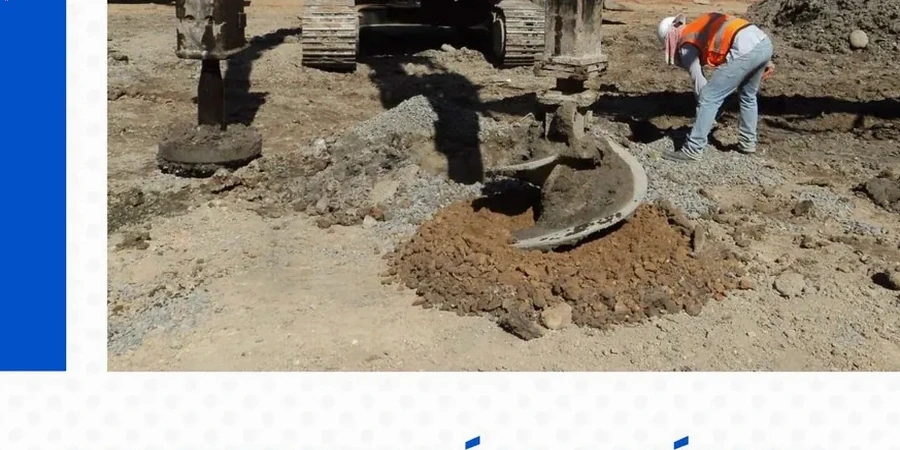
Technical reference image — Miami

Local considerations

A 14-story condominium tower on Brickell Avenue recently encountered a subsurface condition that illustrates the primary risk of stone column design in Miami: the presence of a pinnacled rock surface where the limestone spikes upward to within 10 feet of grade, surrounded by loose sand with a relative density below 35%. Driving a vibrator blindly into this transition zone can deflect the column off-plumb, damage the probe, or — worse — create a preferential seepage path that erodes the sand matrix from around the stone. Our risk mitigation protocol mandates a dense grid of MASW soundings and targeted CPT soundings on 15-foot centers in any area where the Miami Oolite is expected within the column influence zone. We stage the installation sequence from the deepest rock elevation outward, using a bottom-feed system with real-time amperage monitoring to confirm continuous bearing on competent limestone and to prevent the sudden drop in tip resistance that signals a karst void.

Need a geotechnical assessment?

Reply within 24h.

Email: contact@geotechnical-engineering1.org

Technical data

ParameterTypical value
Design ApproachUnit cell concept (Priebe method) with cavity expansion verification
Typical Column Diameter24 to 36 inches (610 to 915 mm)
Replacement Ratio15% to 35% (adjusted for limestone pinnacle avoidance)
Aggregate SpecificationASTM D448 No. 57 or No. 67 open-graded limestone (LA abrasion < 40)
Groundwater CorrectionBuoyant unit weight applied per ASCE 7-22 Section 19
Settlement Reduction Factor2.0 to 4.0 (verifiable by PMT or CPTu before/after)
Liquefaction MitigationApplicable per IBC 1810.2 in loose sands below critical water table

Related services

01

Feasibility and Settlement Analysis

We run three-dimensional finite element models in PLAXIS to estimate the area replacement ratio required to meet the project’s total and differential settlement limits, factoring in the stiffening effect of the limestone pinnacles.

02

Liquefaction Mitigation Design

For sites east of I-95 with clean sands, we design stone columns as drains and densification elements, calculating the improved factor of safety against liquefaction using the Seed-Idriss simplified procedure modified for vibro-replacement.

03

Load Test Program Management

We specify the instrumentation array — settlement plates, multi-point extensometers, and vibrating wire piezometers — and supervise single-column and zone load tests to validate the design modulus before production.

Applicable standards

IBC 2021 Chapter 18 (Soils and Foundations), ASCE 7-22 Minimum Design Loads and Associated Criteria, ASTM D1586 Standard Test Method for Standard Penetration Test (SPT), ASTM D2487 Standard Practice for Classification of Soils for Engineering Purposes, FHWA NHI-16-072 Ground Improvement Methods

Common questions

What is the typical cost range for stone column design and installation in Miami?

In the Miami market, a complete stone column design package — including site investigation, settlement analysis, and construction specifications — combined with installation, typically ranges from US$1,580 to US$5,800 per column, depending on the depth to rock, the replacement ratio, and the need for a pre-drilled pilot hole through the caprock.

How does the Miami Limestone pinnacle topography affect stone column spacing?

The highly irregular rockhead requires a variable grid. We reduce spacing around the perimeter where pinnacles are mapped, and increase it slightly in the softer marl basins, checking the global stiffness with a calibrated unit cell model to prevent a stiff-soft-stiff response under the mat.

Can stone columns be installed in Miami’s high groundwater without dewatering?

Yes, the bottom-feed vibro-replacement method is the standard in South Florida precisely because it allows aggregate placement below the water table without the need for temporary wellpoint systems, provided the platform is stable enough to support the 50-ton rig.

What QA/QC tests confirm that the stone columns are performing as designed?

We specify a combination of post-installation CPTu soundings through the column center, modulus load tests on 2% of the production columns, and installation records that log the amperage and stone volume per linear foot, cross-referenced against the baseline profiles established during the test section.
Location and service area

We serve projects in Miami and surrounding areas.

View larger map